Mechanism design of automatic double edge sealing machine for metal barrel end face filling hole
Chang Zhanli
Metal drums have a long history as packaging for industrial products, and their manufacturing techniques and equipment are relatively popular and mature. However, due to the special requirements of some industrial products for metal packaging barrels, there are still some shortcomings and technical difficulties in barrel making technology. For example, according to the requirements of the International Maritime Export Dangerous Goods Packaging Regulations, many chemical dangerous products such as solid caustic soda must be double-sidedly sealed in a metal barrel, which is difficult to achieve at present.
An example of a typical double edged seal is the two end seals of the tinplate of the can. Moreover, one of the end faces is packaged after being filled with canned food, and in this sense, it is also a double edge of the filling hole which is firmly sealed. In the case of cans such as cans, the existing barrel technology and equipment can only be used for small cans, and it is not suitable for the packaging of large metal barrels such as solid alkali. To meet the packaging of large metal barrels. It is necessary to punch and fold the center of the upper end surface of the metal barrel to form a relatively small filling hole, and after filling the packaged object, cover the small cover for packaging. Because of the limitation of the ductility of the iron sheet, the flange height of the barrel end face can only be about 12mm, so the double side package should be carried out at such a narrow position at the barrel end.
The design of "automatic double edge sealing machine for metal barrel filling holes" (hereinafter referred to as filling hole sealing machine) can not only fill the shortage of chemical products such as solid alkali in China, but also broaden the new application fields of metal barrels. Designing the filling hole sealing machine must be able to solve the following difficulties:
(1) Do not rotate the drum during packaging operations;
(2) The rotating head of the filling hole sealing machine must be able to complete the rotation and feeding actions at the same time;
(3) Crimping, crimping, and parking must be completed automatically and continuously;
(4) The position must be automatically adjusted before the next lid is packaged;
(5) The time for each lid is less than 10s.
After hard work, the filling hole sealing machine was designed and manufactured smoothly according to the above requirements. Since the end of 1992, it has been officially used in the solid alkali production line. After 5 years of actual production test, it proves that the filling hole sealing machine is an ideal. Machines are used by many large factories.
The double side made by the filling hole sealing machine on the filling hole of the barrel end face is shown in Fig. 1. The formation process of the double side is as shown in Fig. 2: the sealing roller is first processed into a curled round edge by a reeling roller which simultaneously rotates around the hole axis and the radial feed is combined, and then the same combined motion rolling roller is used. Finished into a flat double edge.
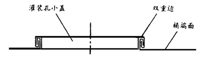
figure 1
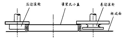
figure 2
The structure of the filling hole sealing machine is as shown in Fig. 3: the motor 1 is fixed on the body and is decelerated by the gears 3 and 20. The gear 19 meshes with a pair of differential gears 8 and 9 having different numbers of teeth. The gear 8 is coupled to the rotary carriage 18 by a key, and the gear 9 is integral with the cam 10. Both the movable slide 17 and the rotary slide 18 are joined together by a radial dovetail groove. The curling roller 12 and the crimping roller 16 are respectively mounted on the two ends of the movable sliding plate 17 by rolling bearings, and the round ends 11 of the same diameter are mounted on the axial ends of the two rollers, and the outer diameters of the two circular wheels are in contact with the cam 10. The filling hole small cover 14 is placed on the central flange hole of the barrel end surface 13, the center positioning head 15 is placed in the recess of the small cover, the shaft head is fixed on the body body, and the rotary sliding seat 18 is supported by the rolling bearing, and the rotation is performed. The sliding seat further supports the cam 10, and the two are slidingly engaged. The bump 7 is fixed on the inner end surface of the gear 9. The push rod contact 5 is mounted in the end face of the gear 8, and the return spring 6 is mounted in the hole. 4 is fixed on the body. The filling hole sealing machine shown in the figure is at the end of the crimping, and the pressing edge is about to start working.
The crimping roller is a disc-shaped roller having a circular arc under the flange. The crimping roller is a disc-shaped roller having a cylindrical body under the flange. The lower end faces of the flanges of the two rollers are in contact with the upper plane of the center positioning head.
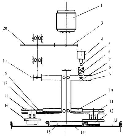
image 3
The cam is of equal diameter, that is, the sum of the radii passing through the ends of the center at each angle is a constant. This constant corresponds to the distance dimension of the two circular wheels relative to the outer circular surface. The centers of the two circular wheels and the cam are mounted on the same line, and this line is parallel to the dovetail groove. When the cam rotates, two round wheels (that is, the moving slide plate and the two rollers) can be driven to perform a linear motion relative to the rotating slide.
The filling hole sealing machine relies on the rotating action, the radial sequential feeding action, and the periodic reset control action to complete the double edge firm sealing operation. To this end, the filling hole sealing machine is provided with two transmission chains to achieve the above purpose. Both drive chains are included in the swivel head. The first is a drive train that meshes the gear 19 with the differential gear on the rotary carriage. This chain only produces a single axial rotational motion, that is, the rotational pressure that drives the two rollers to revolve to form a seal. The revolution is the movement of the metal barrel. The second is a drive train in which the gear 19 meshes with the differential gear on the cam. The chain has two relative movements: one is also a rotational movement relative to the metal barrel, but because the number of teeth of the two differential gears meshing with the gear 19 is different, the speed of the cam and the rotational speed of the rotary carriage are different. Thus, the rotation of the cam relative to the rotating carriage is generated, and the rotation causes the moving slide plate (that is, driving the two rollers) coupled to the dovetail groove of the rotating sliding seat to linearly move in the order of the cam curve. The linear motion is a relative linear motion of the rotary slide and the movable slide, and is also a radial movement of the rotary head relative to the metal barrel, and constitutes a feed motion of the two rollers for sealing operation.
In summary, the filling hole sealing machine mainly has the following relative movements when performing double-side sealing operation on the metal barrel: the first is the rotational movement of the rotary sliding seat as the main body relative to the axis of the metal barrel filling hole; The second is the rotary motion of the cam relative to the rotary slide; the third is the linear motion of the movable slide relative to the rotary slide, and at the same time the radial linear motion relative to the metal barrel filling hole; the fourth is the movement of the rotary head relative to the travel switch .
The automatic switch of the filling hole sealing machine is designed based on the conditions of the second and fourth relative movements described above. When the two differential gears rotate one revolution, it happens to be a cycle of the filling hole sealing machine. This relative motion is a necessary condition for the automatic switch design. It is relatively simple to achieve this condition by simply providing an end face bump on the inner end face of one of the differential gears and a pusher on the end face of the other differential gear to make the bump and push rod distribution radius equal. When the two differential gears rotate relative to one turn, the bump pushes the push rod toward the travel switch, making it possible for the push rod contact to collide with the travel switch.
The relative movement speed of the two differential gears is much smaller than the movement speed of the two relative stroke switches, so that the time for the push rod to remain extended is relatively long. The longer extension of the push rod makes the positional accuracy of the travel switch mounted on the body irrelevant. Similarly, the slower mutual rotation of the differential gears also facilitates accurate resetting of the two rollers. The difference in speed of motion provides sufficient conditions for the design of the automatic switch. Practice has proved that this is an automatic control scheme with simple structure, accurate switching, reliable operation, long service life and extremely low failure rate.
The success of the filling hole sealing machine lies in its ingenious mechanism: it uses only a pair of differential gears to realize the whole process sequential action and control of the whole machine, that is, simultaneous rotation action, curling and crimping action, reset action And control actions of the work cycle.
The filling hole sealing machine has a wide range of applicability, and it can also be used to package large barrel end faces filled with material without rotating the barrel. This is also a feature that goes beyond the existing barrel technology.
With minor modifications, it can also be rounded and multi-edge sealed.
In addition to the use of barrels, its mechanism has a wide range of promotional values ​​in the field of metal cutting and non-cutting processing. Two examples are as follows:
(1) It can be used for steel pipe end groove cutting machine. The groove cutting machine designed by this mechanism can be used on the construction site, clamped on the steel pipe, and cut the groove, and can complete the rotation and the feeding action at the same time, the structure is simple, the volume is small, and the operation is convenient;
(2) It can be used for the reduction molding machine of thin-walled stainless steel pipe. It automatically processes the decorative stainless steel pipe with complex curve shape on the straight pipe. It automatically reduces the diameter along the axial and radial directions of the steel pipe, and has high processing precision and is very easy. operating.
Whether you consider yourself to be a baking genius, a culinary artist or a complete catering novice, nylon kitchen utensils will stand the test time and last for many years to come. Tough, durable and safe to use, nylon kitchen utensils are the real workhorses of the kitchen and they can stand the test of time.
- Wear and tear – wear and tear happens to everything we own, including items we use outside of the kitchen, so this is just a very natural process to expect. But when it comes to choosing utensils, nylon kitchen utensils are recognised to have a much tougher shell.
- Stick resistance – nylon kitchen utensils are best known for their stick-resistant or non-stick properties, making them ideal for both baking and cooking. They never damage the pots and pans that you use them and because of their stick resistance, they`re easy to clean.
- Cooking safety – nylon kitchen utensils can resist bacteria much better than your average spoon or spatula, and is completely safe to use in food preparation and cooking.
Nylon Kitchen Utensils,Nylon Spoon,Nylon Utensils,Nylon Cooking Utensils
Yangjiang Superwins Trade Co., Ltd. , https://www.steelkitchenware.nl